With this modification you will be able to control the power output of any device that uses GL2422MP miniPCI wireless card in a range from -13 to 17dbm on AP mode and -11 to 19dbm on the other modes. Some devices that use Global Sun’s GL2422MP miniPCI is D-link DWL-810+, DWL-800AP+ and DWL-900AP+.
Power output of GL2422MP is control by a TI (TNETW1100B) chipset. The chipset is driving various voltages on MAX2820 transceiver’s pin (TX_GC) which controls the amplitude of the transmited signal. By altering the TI’s Digital to Analog Converter operation range, we can change the range of the output power to fit our needs (see Datasheet MAX2820). In order to do this, we can simply modify the voltage divider connected to TI’s TX Gain Control output pin which converts the output current of the DAC into input voltage for MAX2820. Placing a potentiometer in parallel with the resistor between Vcc supply voltage and Vtx_gc we can control the power output of GL2422MP without having to remove any SMD components thus we don’t destroy the device. If we wish to rebuild the device to its original operation we can simply remove the potentiometer and it will work the same way as it did before the modification.
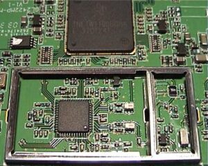
In order to have a handy control over output power but also maintain the lowest possible voltage (0.85Volt) on the same levels I choose a logarithmic potentiometer at 10kOhms. Open a hole on the side of the device’s box and fasten the pot there with a nut. Remove the miniPCI from its slot and also remove from it the metal cap which protects the RF section of the PCB. There is a small opening between the two exposed metal compartments. Two thin cables will pass through this hole and get soldered across the resistor of the voltage divider. I opened this hole a bit more with a small screwdriver because my cables couldn’t pass through it. These tiny cables are soldered on the resistor with extra caution from one side and on the potentiometer on the other side in series with a 330Ohm resistor. This resistor is placed in order to limit the voltage divider’s maximum voltage at 2 Volts (supply 2,85V) where we have the maximum attenuation of -13dbm. The potentiometer should be connected in a way that increases resistance anti-clockwise and decreases clockwise. Short-circuit the unused pin of the pot with the center pin to capture less noise from it. Assemble the device back. Be careful with the internal antenna not to touch and short-circuit any parts as you close the cap. Remove the antenna if necessery.
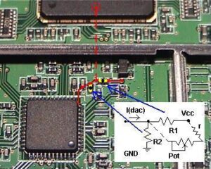
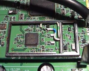
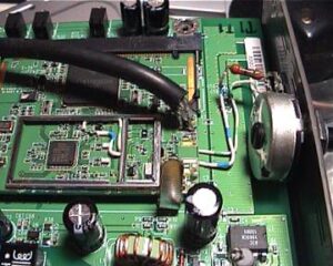
Input voltages for TX_GC pin before the modifications were varying from 0.89V to 1.2V through Global Sun’s driver software and only for AP mode. This value are interpreted as 19 to 8dbm output power.
Now, with the potentiometer, the voltages can vary from 0.85Volt to 2Volt for all modes while for AP mode, software power control still works but for a different range (exaple: 1.5 to 2Volt). This means that now output power can vary from 19dbm(79mW) to -13dbm(5nW!!!)
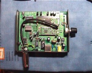
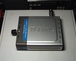
You can find out how much power your device outputs by measuring the voltage TX_GC with a multimeter and correspond it to the values given in MAXIMs Datasheet.
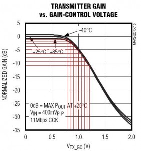
For my device (DWL-900AP+) in Client mode with pot I measured:
| power_pot | Voltage (Volt) | Attenuation (db) | Power output (dbm) |
| Full left | 1.83 | -31 | -11 |
| 9:00 | 1.48 | -20 | 0 |
| 10:30 | 1.28 | -15 | 5 |
| 12:00 (middle) | 1.14 | -10 | 10 |
| 1:30 | 0.96 | -5 | 15 |
| 3:00 | 0.85 | -2 | 18 |
| Full right | 0.75 | -1 | 19 |
Good Luck… 😉
